Getting Started
This guide provides a basic walkthrough of creating a simple quantum circuit — the Hello World of quantum computing: a Bell state preparation circuit.
Tutorial: Creating Your First Quantum Circuit
Creating a New Circuit
- Open Circuit Designer ⧉
- Click New Circuit
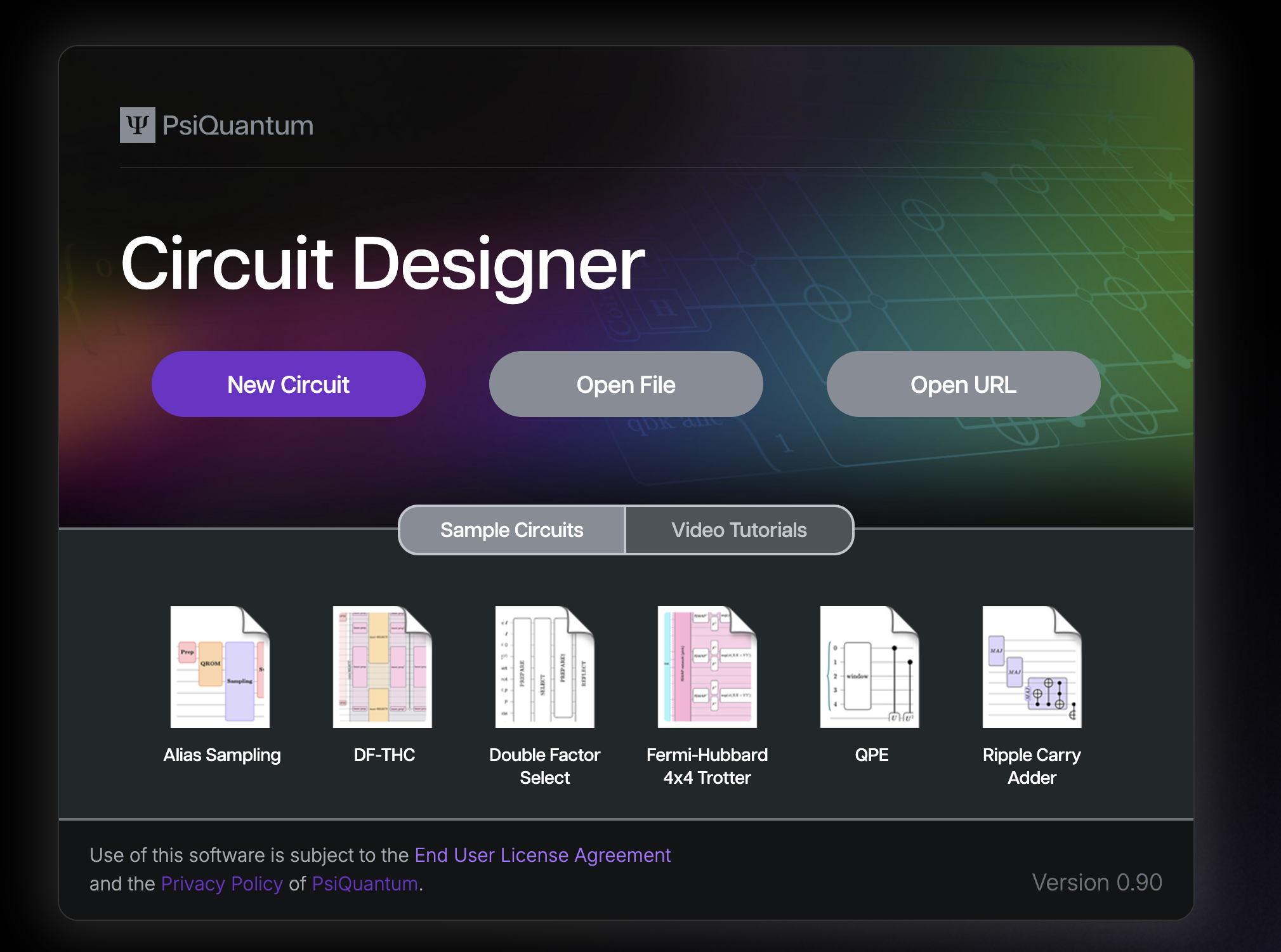
- An empty canvas will appear with a space ready for you to create your first circuit!
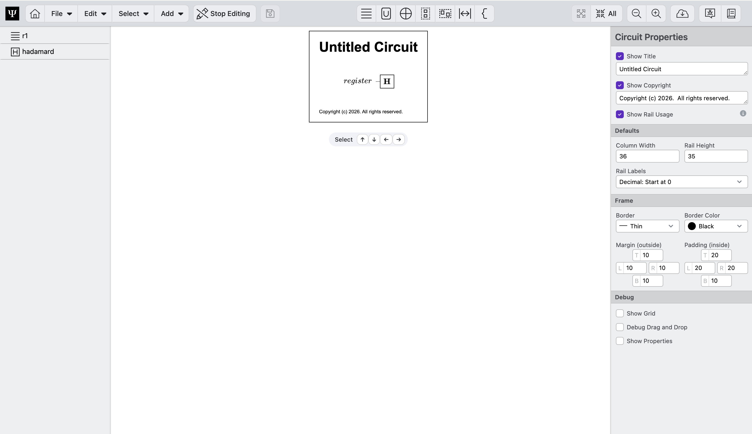
Update the Title
Every circuit diagram should have a clear, descriptive title so readers immediately understand its purpose.
To add or update the circuit title:
- Click on an empty area of the canvas so no circuit elements are selected
- In the Properties panel on the right, locate the Title field and type a
Bell State Pairs
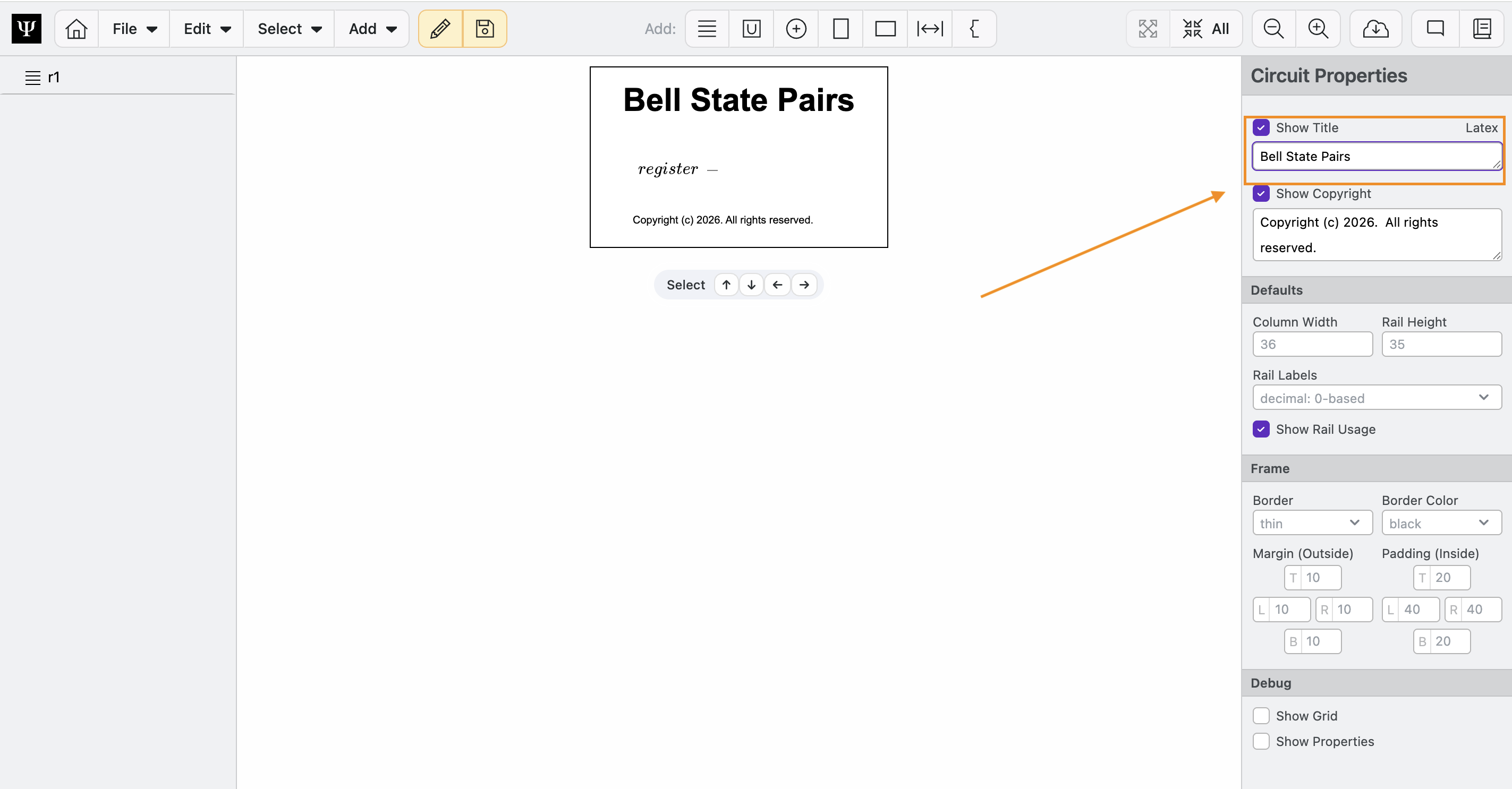
Note that the circuit properties tab also lets you add a copyright, adjust document properties, and enable Debug features.
Adding your First Register
Registers are at the core of quantum circuit diagrams. They are the horizontal lines that represent how one or more quantum bits evolve with time (left to right). In Circuit Designer, you can freely add, reorder, and name any number of registers. Additionally, registers can be split into components, called rails, which represent individual qubits, or other components of the register.
One register is automatically added after creating a new circuit. Follow these steps to customize it:
- Click on the
r1register - In the Element Properties panel that appears on the right hand side of the screen:
- Type
\ket{a}in the Label field - Select
Customfrom the Rail Labels radio buttons - Type
1,2,...,nin the Custom field to create n qubits (a.k.a. rails) in the register.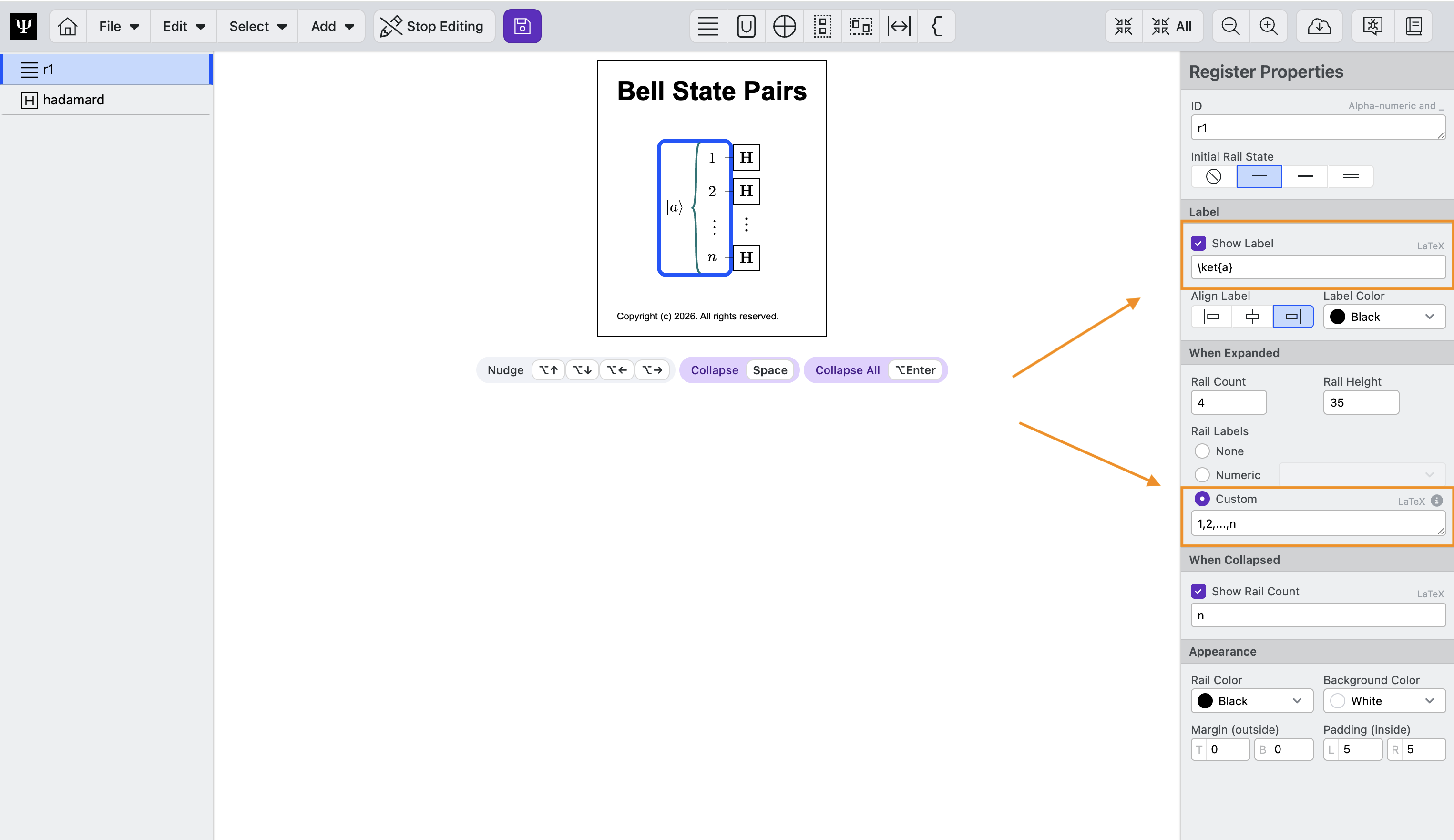
- Type
Duplicating Registers
- Select the
aregister by clicking on it.- Press ⌘C (or ctrl + C) to copy it. You can also copy by clicking Edit > Copy
- Press ⌘V (or ctrl + V) to paste a copy. You can also paste by clicking Edit > Paste
- We will relabel it to
bin the Properties panel, by typing\ket{b}in the Label field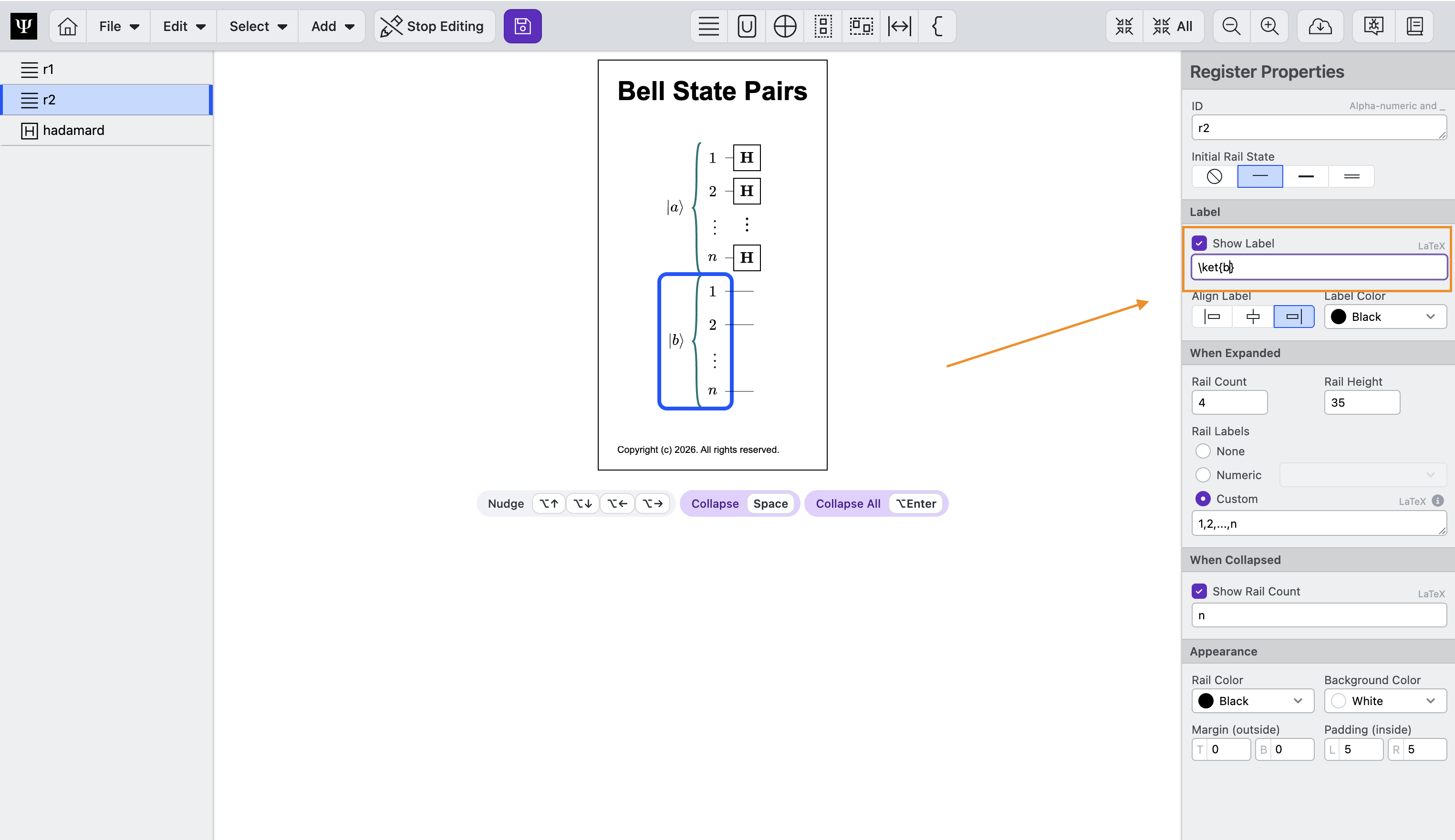
Adding Registers
You can also add registers by clicking Add> Register or by typing ⌘1 or ctrl + 1 on Windows.
Adding a CNOT Gate
Gates are the fundamental computation unit in quantum computing. Circuit Designer begins all new circuits with a Hadamard gate already added on the first register. For our Bell State, we first need to add one CNOT gate after the Hadamard gate.
- Select the
bregister by clicking on it. - Select Add > Gate from the menu, or type ⌘3.
- A
Hadamardgate appears on thebregister (it will appear on the last selected register) - If the
Hadamardgate does not appear on thebregister, you can adjust the rails it is on by first selecting the gate then either:- Clicking and dragging the gate to the
bregister. - Nudging the gate to the
bregister by clicking ⌥↑ or ⌥↓ to move the gate up/down a single rail at a time. - Clicking
enterand click on the rails it should be on. Note that the click command will toggle between adding the gate, adding controls, and removing the gate. - Setting the Target Register to
r2in the Properties panel. Registers have both an ID and a Label. The ID is used to assign gates to specific registers. We recommend using short IDs. The Label is a field that accepts LaTeX text as input and is used to style the diagram.
- Clicking and dragging the gate to the
- Now let's turn this new
Hadamardinto aCNOT. In the Properties panel:- Select
CNOTas the Gate Type - Hold enter and click on rails to toggle states. Ultimately, you want to have the target on the first rail of b,
r2[0], and the control on the first rail of a,r1[0]. See Click to set Rails for more details. - Alternatively, set Target Rails and Control Rails manually in the Properties panel to
r2[0]andr1[0]
- Select
Addressing Rails
You can address specific rails by labeling them within brackets. For example, if you only want to apply the Hadamard gate to rails 1 and 2, you can enter r1[1,2] into the Rail Names field. Enter * to assign the gate to all rails. Circuit Designer uses python list conventions for accessing specific rails. See Addressing Rails for more details.
Duplicate the CNOT Gate twice
Duplicating and Nudging circuit elements is often the fastest way to build a circuit diagram. Practice by following the following steps:
- Click on the
CNOTgate - Enter ⌘D to Duplicate the gate
- Enter ⌥↓ to nudge the gate down one rail
- Enter ⌘D to Duplicate the gate
- Enter ⌥↓ to nudge the gate down two rails
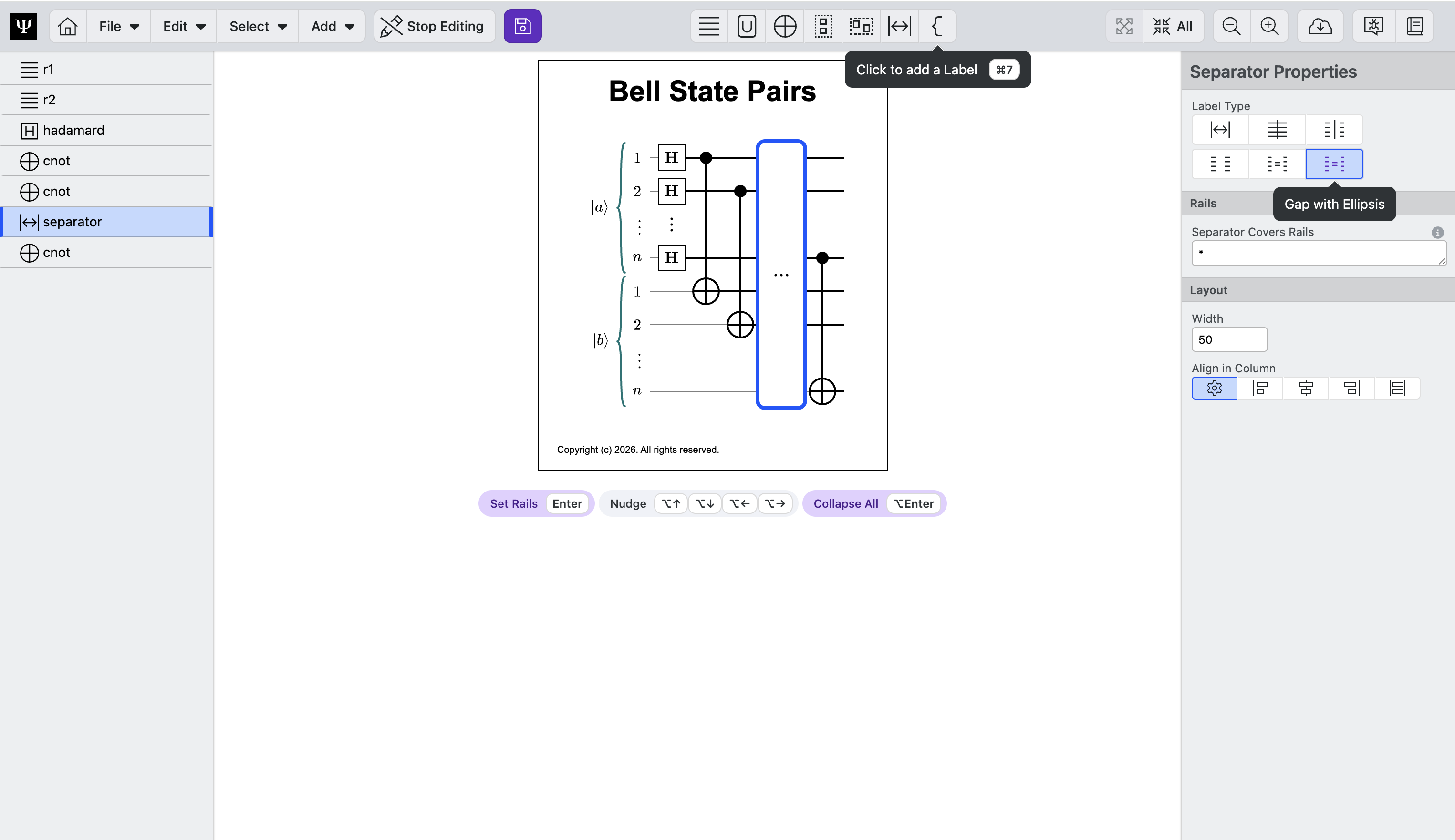
Adding an ellipsis
Sometimes you want to add ellipsis to a circuit to indicate that an operation is repeated. We can do this by adding a Separator circuit element and adjusting the type to ellipsis.
- Select Add > Separator
- If necessary, nudge the separator into place by selecting the separator and entering ⌥← or ⌥→
- In the Properties panel, set Seperator Type to
Gap with Ellipsis
Wrap in a Routine
Now that we have established our registers and added gates, we will want neatly organize the operations into higher level operations. In Circuit Designer, we can do this with Routines.
- Hold Shift and Click all gates to select them. Note, you only need to click the first and last gates to select everything in between.
- Click Add > Wrap in Routine in the top menu, or enter ⌘⇧G. All of the circuit elements will be added to a single Routine. Note, the Routine will expand and contract to fit all circuit elements within it.
- We will rename it in the Properties panel: Type
\text{Bell Pairs}in the Label
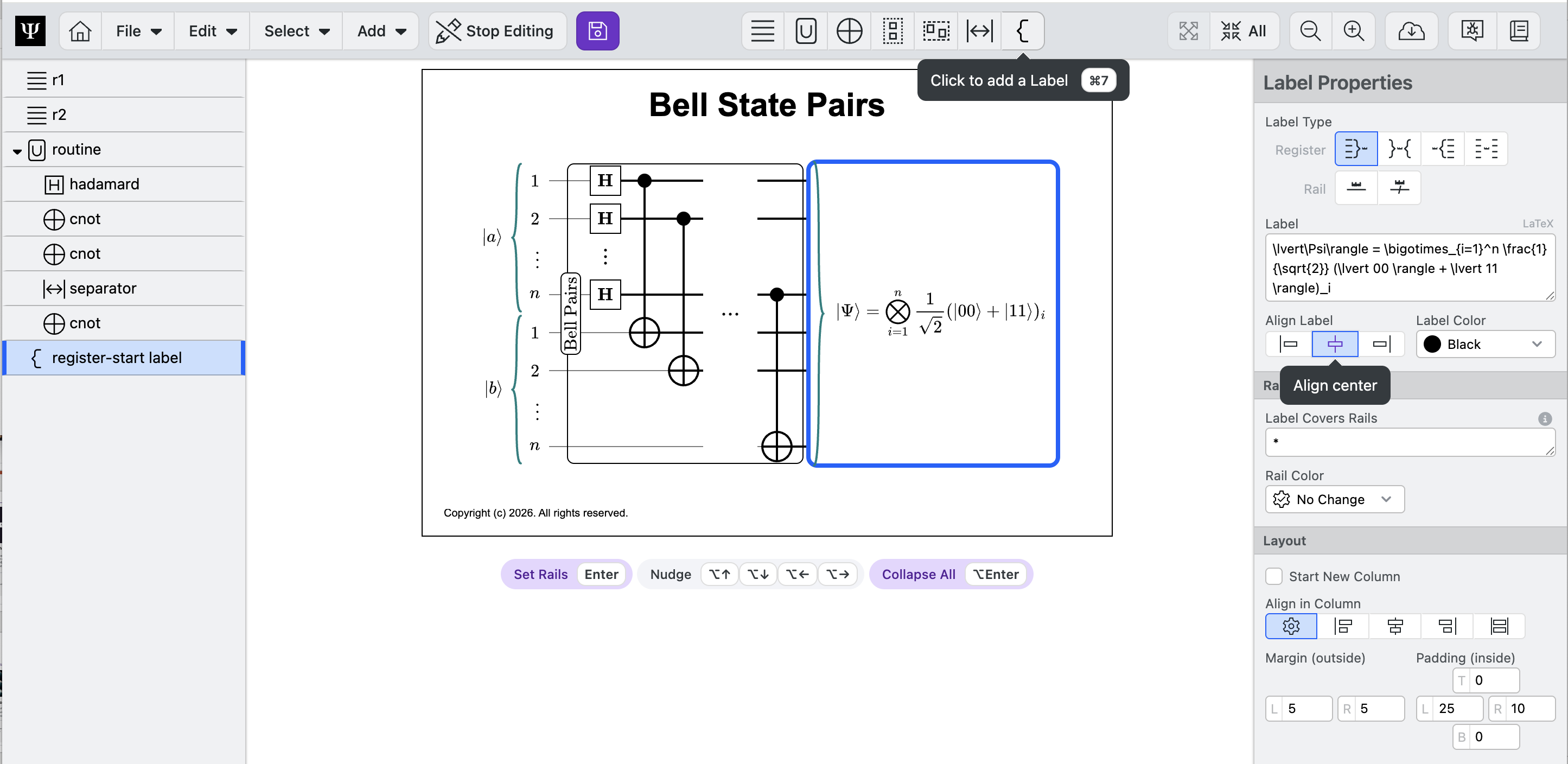
Add a Label
Now we can label the end state of the quantum circuit.
- Click Add > Label
- Move the label to the end of the circuit
- In the Properties panel:
- Set Label Type to
Register label with curly on left - Enter
\lvert\Psi\rangle = \bigotimes_{i=1}^n \frac{1}{\sqrt{2}} (\lvert 00 \rangle + \lvert 11 \rangle)_iin the Label field
- Set Label Type to
Customize with Color
Finally, we can add color to our circuit diagram to give it some style!
- Select the
Bell Pairsroutine - In the routine Properties, set the Background to
Purpleunder Appearance - Continue to customize your circuit! Each circuit element can be customized.
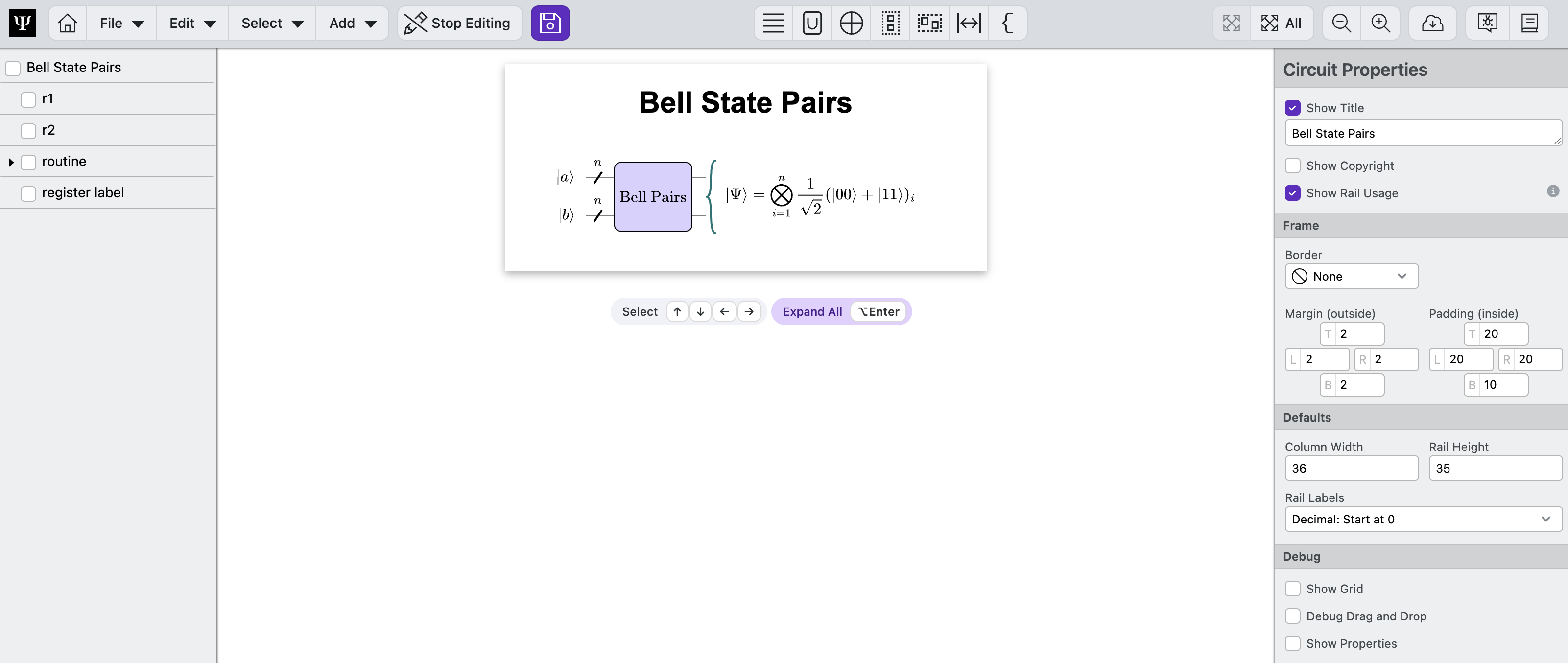
Interactive: Expand and Collapse
Diagrams are not static images, but interactive objects.
- Double-click the
Bell Pairsroutine label to expand and collapse it. - Double-click the
aregister to expand and collapse it. - Note that the space will expand and collapse the selected node.
- Click Expand All and Collapse All to toggle all elements
Download and Save
Now we can export our circuit diagram.
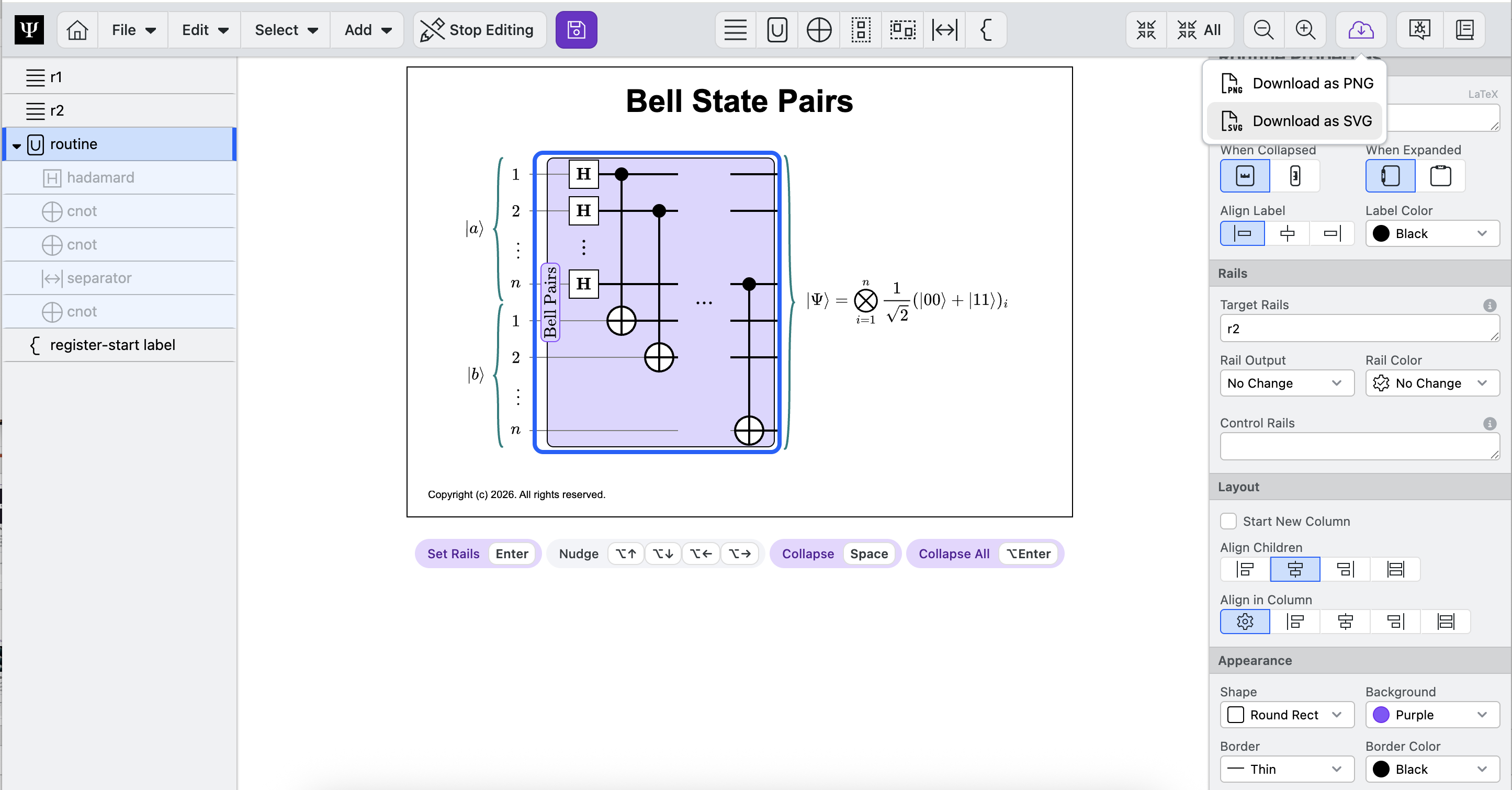
- Click Download button > Download as SVG to download an image of your circuit onto your computer. You can collapse and expand elements to change the image.
- Click Save to save to your desktop
Sign In Required To Save Files
You need to be signed into Circuit Designer to save diagrams. Circuit Designer does not store your data, you have to save your circuit in order to keep your files. We recommend saving early and often.
Congratulations! You've created your first quantum circuit - a Bell Pairs state preparation circuit, a building block for FTQC applications.
Next Steps
Learn about the Circuit Designer's home page.